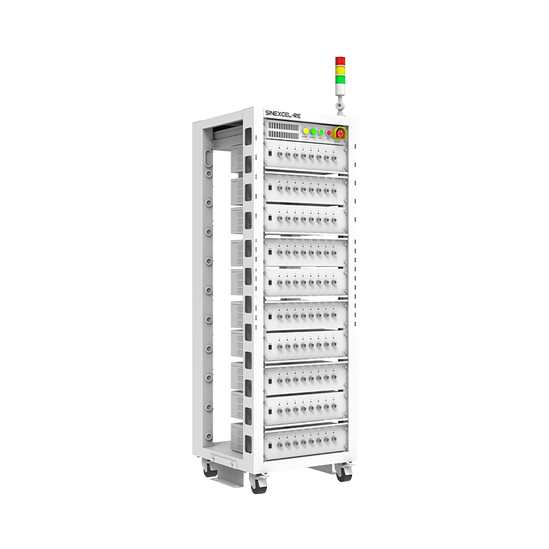
High Performance EV Battery Test System
charge:-6V-6V
discharge:-6V-6V
voltage accuracy:0.02%F.S.
current accuracy:0.02%F.S.
discharge:-6V-6V
voltage accuracy:0.02%F.S.
current accuracy:0.02%F.S.
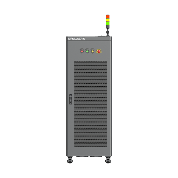
Battery Module (60v-300v) Test System
charge:5V-60V/150V/300V
voltage accuracy:0.02%F.S.
current accuracy:0.02%F.S
voltage accuracy:0.02%F.S.
current accuracy:0.02%F.S
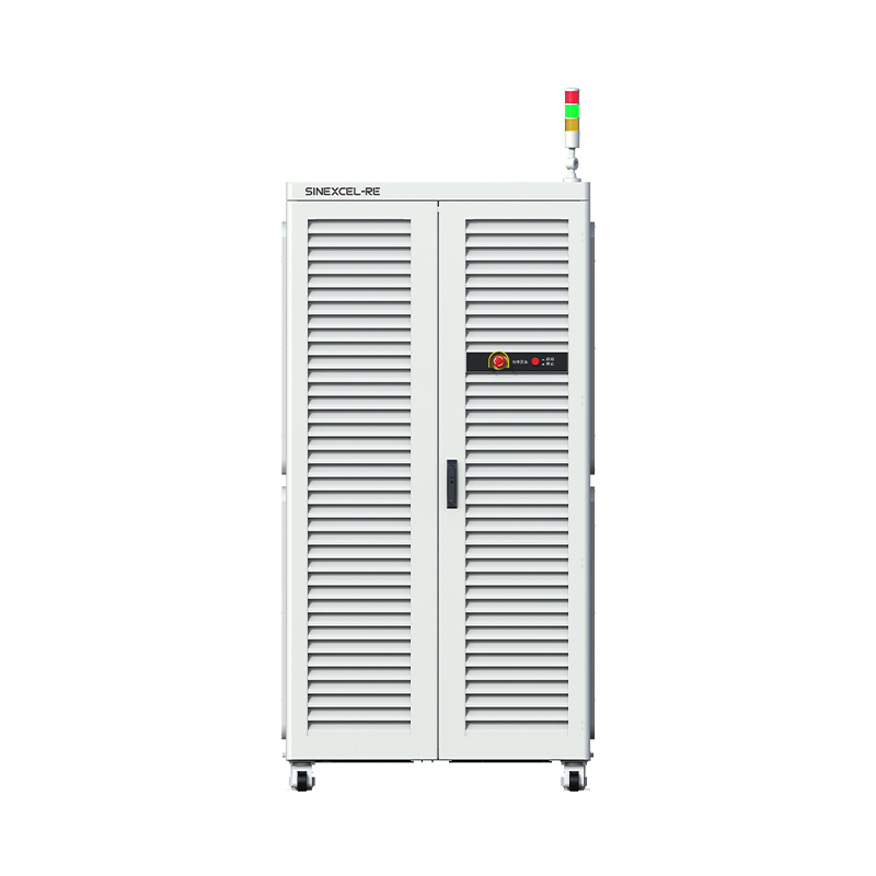
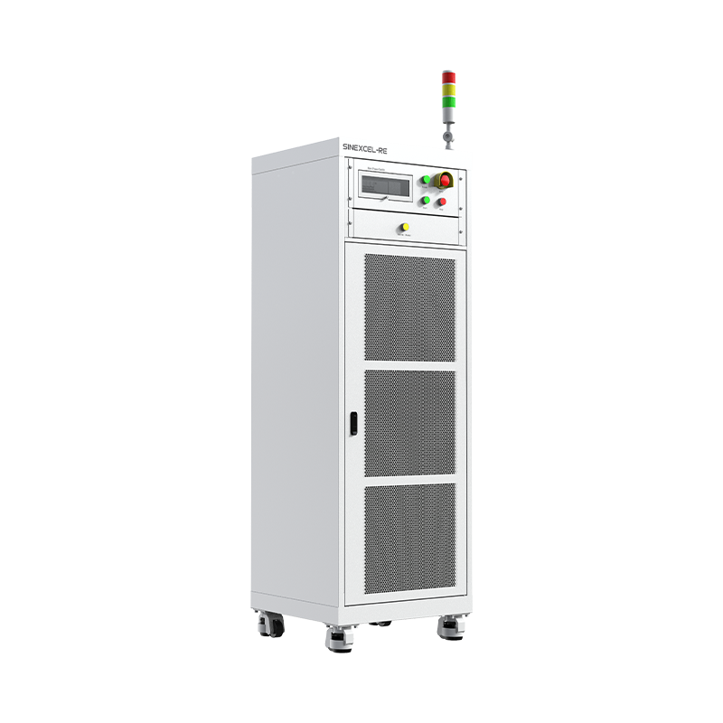
Battery PACK (500v-1000v) Test System
charge:10V-1250V
voltage accuracy:0.02%F.S.
current accuracy:0.02%F.S.
voltage accuracy:0.02%F.S.
current accuracy:0.02%F.S.
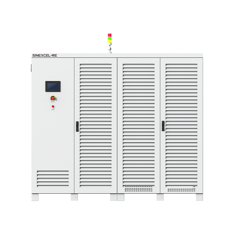
High-Volt Storage Battery Cluster Test System
charge:50V-1700V
voltage accuracy:0.03%F.S.
current accuracy:0.03%F.S.
voltage accuracy:0.03%F.S.
current accuracy:0.03%F.S.
Milliampere-Level Test System
charge:-5-5V
discharge:-100mA~100mA
voltage accuracy:0.01%F.S.
current accuracy:0.02%F.S.
discharge:-100mA~100mA
voltage accuracy:0.01%F.S.
current accuracy:0.02%F.S.
IT Battery Test System
charge:0~5V
discharge:1~5V
voltage accuracy:0.02%F.S.
current accuracy:0.05%F.S.
discharge:1~5V
voltage accuracy:0.02%F.S.
current accuracy:0.05%F.S.
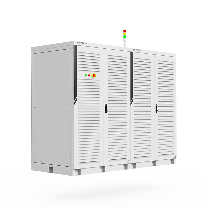
EV Battery Test System
charge:0-5V
discharge:1-5V
voltage accuracy:0.02%F.S.
current accuracy:0.02%F.S.
discharge:1-5V
voltage accuracy:0.02%F.S.
current accuracy:0.02%F.S.