- Home
- »
- Battery Module (60v-300v) Test System
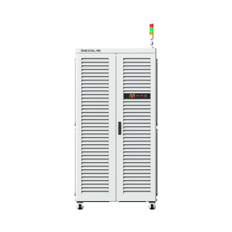
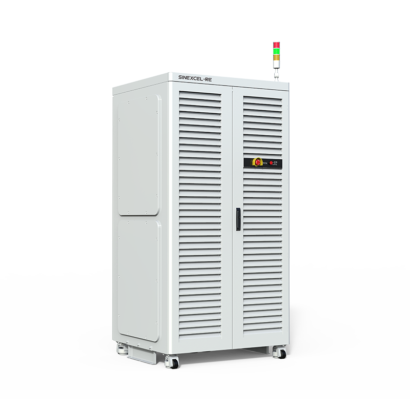
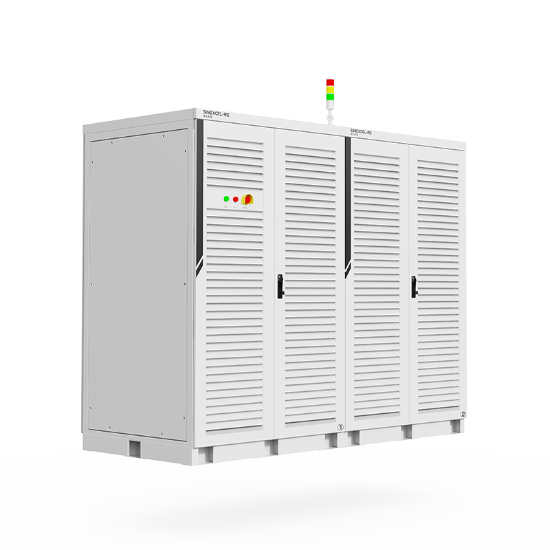
Battery Module (60v-300v) Test System
Battery Module (60v-300v) Test System has the characteristics of energy feedback, high precision, fast response, high safety, and ease of use. It is suitable for various purposes such as product research, product verification, and quality control of module testing system
Detailed Introduction
The module test equipment adopts SINEXCEL-RE advanced high frequency isolation scheme, and the detection process supports multi-gear switching. The equipment integrates voltage, temperature, pressure and other auxiliary channels, and can also integrate temperature box, water cooler and other equipment, 20ms high-speed working condition simulation and other practical innovative functions to meet all aspects of battery electrical performance testing.
System Features
Key System Parameters
Model |
Voltage Parameters | |||
|---|---|---|---|---|
Output Voltage | Charge And Discharge: 5V~60V/150V/300V | |||
Voltage Accuracy | ± 0.02%F.S. | |||
Voltage Resolution | 0.1mV |
Current parameters |
|---|
Output Current Range |
-100A ~ +100A |
-200A ~+200A |
-300A ~+300A |
-600A ~+600A |
-1200A ~+1200A |
|---|---|---|---|---|---|
Current Rating | / | 100A/200A | 100A/200A/300A | 100A/300A/600A | 200A/400A/800A/1200A |
Voltage Accuracy |
± 0.02%F.S. (Based on current range) |
|---|---|
Current Resolution | 0.1mA |
Channels Quantity | 2CH/4CH/8CH/12CH/16CH (Support for customisation) |
Power Parameters | |
|---|---|
Power Of The Whole Machine | 48KW~480KW (Support for customisation) |
Charge And Discharge Test Parameters | |
|---|---|
RiseTime | ≤2ms |
Switching Time | ≤5ms |
Minimum Recording Time | 10ms / 1mV / 1mA |
Charge-discharge Operation Mode | CC, CV, CP, CC-CV, CR, DCIR, Pulse, Drive simulation and other modes |
Drive Simulation For EVs | 20ms operating condition, 10 million+ lines of text, support Excel import |
Channel Parallel | Supports parallel connection of 4800A (channel current accuracy after parallel connection meets ±0.02% F.S.) |
Efficiency | Charge efficiency: 92%; Feedback efficiency: 92% |
Battery voltage exceeds the upper voltage limit, confirmation time 0.2s
- Use a multimeter to measure the actual battery voltage and compare it with the voltage displayed on the BTS to check if the sample values are consistent.
- If the sample value and the actual value are not equal, confirm whether the issue is with the DC board or the wiring by swapping the sampling lines with adjacent channels. If the wiring is faulty, check for incorrect, loose, or poor connections in the voltage sampling lines.
- If the sample value and the actual value are equal, check if the upper computer step settings are reasonable and determine if the battery overvoltage occurs as soon as the step runs or at a specific point during the step.
- Check the corresponding battery for any obvious swelling, damage, or other abnormalities. If there are issues, take necessary safety measures.
- If the battery and voltage sampling lines are normal, confirm that the DC board is faulty and replace it.
Battery voltage is lower than the lower voltage limit, confirmation time 0.2s
- Use a multimeter to measure the actual battery voltage and compare it with the voltage displayed on the BTS to check if the sample values are consistent.
- If the sample value and the actual value are not equal, confirm whether the issue is with the DC board or the wiring by swapping the sampling lines with adjacent channels. If the wiring is faulty, check for incorrect, loose, or poor connections in the voltage sampling lines.
- If the sample value and the actual value are equal, check if the upper computer step settings are reasonable and determine if the battery undervoltage occurs as soon as the step runs or at a specific point during the step.
- Check the corresponding battery for any obvious swelling, damage, or other abnormalities. If there are issues, take necessary safety measures.
- If the battery and voltage sampling lines are normal, confirm that the DC board is faulty and replace it.
Module 6S does not receive data from the upper computer, switches to fault state. The fault is automatically cleared when the module receives data from the upper computer.
- Check if the module and the middle computer are in a normal powered-on state.
- Check if the CAN connection between the module and the middle computer is normal.
- Check if the CANA dip switch is set correctly.
- Measure the matching resistance between CAN H and CAN L on the CANA bus. It should be 60±5 ohms. If not, adjust the matching resistance on the signal adapter board. If the bus voltage is normal, check the BTS fault records to identify which sub-channel triggered the fault. Use debugging software tools to check if the bus voltage displayed for that channel is normal. If abnormal, it can be determined that the DC board's bus sampling is faulty, and the board should be replaced.
- If all the above points are normal, connect a CAN box and use the captured messages to determine whether the issue lies with the middle computer or the lower computer.
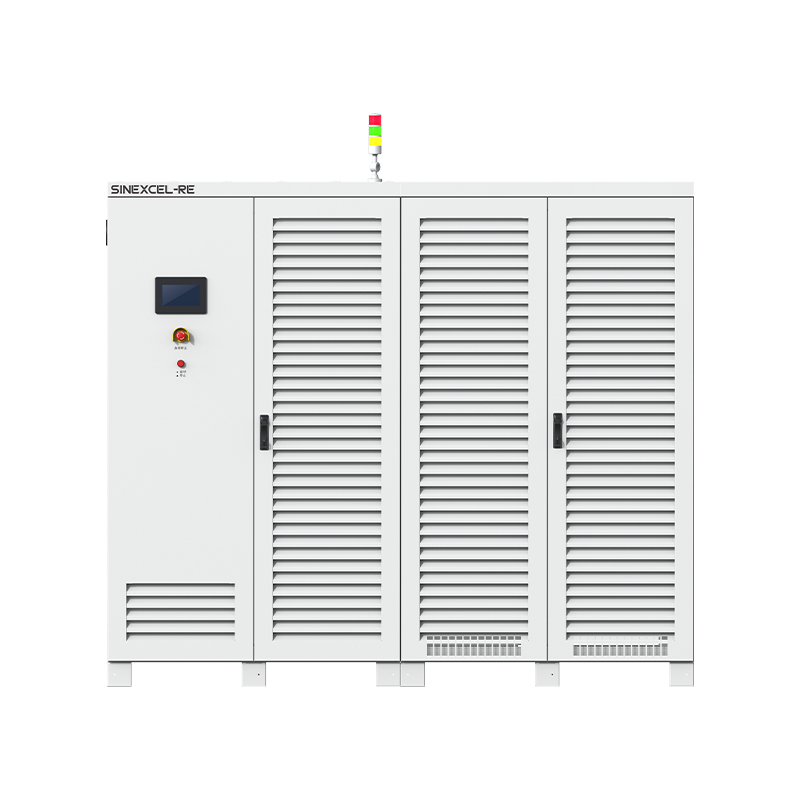
Our Products
Our range of battery test equipment includes various specialized test systems such as the Milliampere-level Test System, IT Battery Test System, and EV Battery Test System, among others
High Performance EV Battery Test System
discharge:-6V-6V
voltage accuracy:0.02%F.S.
current accuracy:0.02%F.S.
Battery Module (60v-300v) Test System
voltage accuracy:0.02%F.S.
current accuracy:0.02%F.S
Battery PACK (500v-1000v) Test System
voltage accuracy:0.02%F.S.
current accuracy:0.02%F.S.
High-Volt Storage Battery Cluster Test System
voltage accuracy:0.03%F.S.
current accuracy:0.03%F.S.
Milliampere-Level Test System
discharge:-100mA~100mA
voltage accuracy:0.01%F.S.
current accuracy:0.02%F.S.
IT Battery Test System
discharge:1~5V
voltage accuracy:0.02%F.S.
current accuracy:0.05%F.S.
EV Battery Test System
discharge:1-5V
voltage accuracy:0.02%F.S.
current accuracy:0.02%F.S.
Let’S Build The Future With Innovation.
Please Provide The Following Details To Help Our Sales Representativesbetter Understand Your Needs And Get In Touch With You As Soon